


Tips And Tricks In Searching For An Optimal Monitoring Solution For Your Data Centre
10 February 2023
Picture a situation that often occurs in real life: Administrator Max Z. has been commissioned by his data centre manager to create a recommendation for a monitoring solution for both environmental and power conditions. He needs to identify business specifications, available monitoring solutions, and which systems should be shortlisted for consideration. During this process we look over Max Z.'s shoulder and get into his thought process:
Why is it always me?!? Why has this landed on my plate!?! Okay, it‘s my job and complaining doesn‘t help. We need a monitoring solution for our data centre. Before I start researching wildly on the web and get completely overwhelmed by the abundance of offers as well as the numerous functions, features and benefits, I need to focus. I’ll start with the features we need most:
- We would like to have the ability to permanently monitor all vital power data at every distribution level, as well as environmental conditions such as temperature, humidity and differential pressure at the room, row, rack and location within a rack.
- The monitoring tool should also act as an early warning system that warns us of critical changes in power values and environmental conditions so we can prevent system malfunctions and failures.
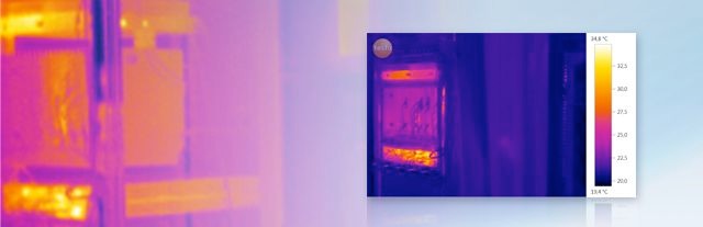
- The system should detect thermal weak points in our environment in order to better distribute loads and save energy.
- The underlying data must be reliable and accurate enough to calculate PUE to compare our energy efficiency against other data centres.
- More importantly, we need to develop our own parameters that track the relationship between IT performance, energy consumption and CO2 emissions to report our data centre’s energy efficiency and sustainability progress over time.
Specific requirements for the monitoring solution
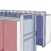
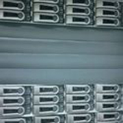
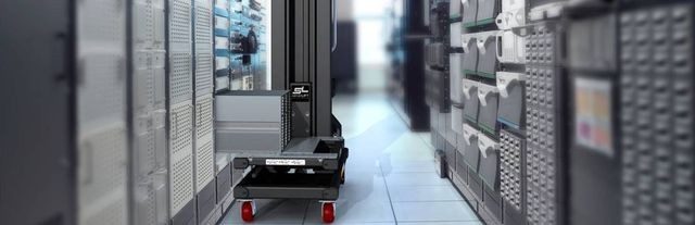
With the overall busines requirements set, Max looks more specifically at what they should monitor: There are a total of ten rack corridors in our data centre, with the cold aisles being contained. The power distribution to the racks takes place via the ceiling with a busbar system with a redundant design. An A and B supply line is set up in the racks via PDU power strips for the active IT devices. We need to track power metrics for each device, especially the business-critical IT hardware. We are also interested in the total load per rack and the control of power consumption and utilisation of distributions and outlets.
The contained cold aisles are of particular importance for monitoring the ambient conditions. Monitoring the cooling air pressure is important here. Finally, it is important to prevent the fans of the servers in standby mode from starting to move if the air pressure is too high, which can damage the hardware. We also have to keep an eye on the humidity, because if it is too high, the servers have to regulate the condensation, which means higher energy consumption. If the humidity exceeds the values specified for the server over a longer period of time, this can possibly even lead to corrosion, system malfunctions or failures. If it is too dry, in the worst case we may have to deal with short circuits in the IT hardware. Of course, we also need to know the temperatures inside and outside the contained aisles so that we know how efficiently we are cooling. If we find that the supply air temperatures are too low, we can adjust to avoid excessive loads and costs of cooling.
Installation and security wish list
Since my colleagues and I have to install, set up, maintain and, if necessary, expand the entire monitoring system, there are a few more items for my wish list. We already have an existing DCIM system. It should be possible to integrate the management of the new monitoring solution into that. What we definitely don't want is to have to work with isolated solutions and proprietary management tools for the environmental and power metrics.
Also, I don't want to have to lay miles of cable during installation. Nor do I want to configure hundreds of measuring modules and sensors individually. The total setup effort should be kept within reasonable limits in terms of work and time. The same also applies to system maintenance and future additions when needed.
Another important aspect is security. As with other applications, we need user and access rights that we can define individually. Data communication should be encrypted and of course we need backup options to avoid data loss. It would be ideal if the monitoring system, like our entire infrastructure, could be set up with a kind of redundant safety reserve in order to be able to receive the data even in the event of short service interruptions and planned or unplanned downtime.
What's on the market?
Now that Max has a solid list of requirements he looks at what’s available. After extensive online research, initial discussions with various providers and reading specialist articles, Max reaches several conclusions:
- There are quite a few monitoring system manufacturers with diverse types of solutions and functionality. They generally consist of a hardware and software or web-based management system. The power monitoring sensors measure either as independent devices or integrated into PDU power strips.
- Depending on the requirements and the choice of solution, a selective or extensive monitoring structure can be set up at the device, room, building and location levels.
- For many of the solutions, the individual sensors are connected to one another via a copper cable route in a daisy chain format. These are practical when a manageable number of monitoring modules are to be installed locally.
- Bus systems are available for recording and checking current and environmental parameters directly in the rack. The corresponding measurement sensors are connected to a bus interface in the cabinet and their signals are then looped through from rack to rack to a central administration unit.
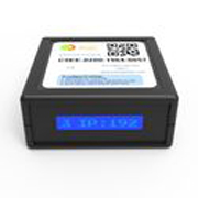
- Radio-based wire-free monitoring systems offer a special feature. There is no physical connection between the individual measurement modules. They communicate with each other by radio and form a mesh network. A special gateway is used for data collection and distribution. This wireless solution is from Packet Power, which can be obtained from the data centre specialist Daxten. Using a dynamic radio wire-free network, it receives the data from the measurement modules and forwards them via common open protocols such as SNMP or Modbus TCP/IP to a system-specific management interface or to any BMS or DCIM application.
- Most of the hardwired and bus solutions also communicate with a data centre or building management system (BMS) via open protocols. But before the data can flow and be analysed, extensive installation work is required.
Start-up and setup differences between wired and wire-free systems
In cable-based systems, the "daisy chain" is first installed by hand by attaching the individual sensor modules in or on the rack using appropriate assembly kits and finally connecting each module via a cable section to the central system management unit at the beginning and the end of the string. Very simple systems only offer a proprietary administration interface, through which individual identifiers and access authorisations can be configured manually for the measurement modules. More demanding wired solutions as well as bus-based systems allow the modules to be addressed via TCP/IP and also offer the option of automatically assigning access rights using existing user databases.
Wireless systems seem to be particularly elegant to implement. With the Packet Power solution just mentioned, the radio wire-free measurement modules automatically configure themselves after being switched on and logged into a dedicated radio network. They start their measurement activities independently. The wire-free network is formed by the measurement modules and gateways. All system modules in the wire-free network are recognised via a central management tool, provided with an ID and managed user and access rights can be defined individually.
Wiring, cabling and radio
The amount of time and work required to install cable-based solutions varies by the type of monitor. Environmental sensors for temperature, pressure and humidity are relatively easy to place on rack fronts and rears or mount using brackets. Power sensors either need a cable connection to suitable PDU power strip in the rack or integration into the power strip.
Individual device level monitoring must either be prepared for current monitoring, which is only the case with very few devices in the inventory, or third-party energy meters must be used. To measure power values on busbars in the spatial distribution, modules must be retrofitted in the tap-off boxes and the feeders, hardwired and routed along the busbars to the central administration unit via communication cables.
The situation is similar with the control cabinets and switchboards that are to be integrated into the power monitoring system. Here the cable harnesses with the current transformers are to be placed on the conductors and the corresponding data cables are to be pulled. Of course, both require an expert hand, longer planned downtime and the temporary risk of not having the redundant power supply path available for the duration of the installation.
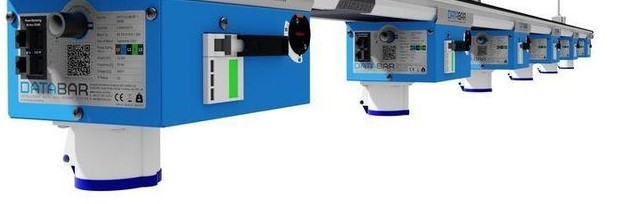
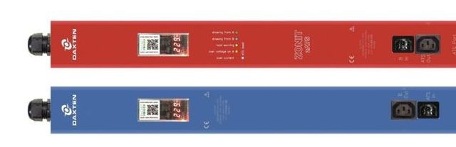
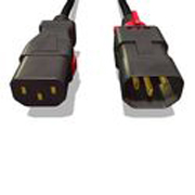
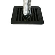
Wireless monitoring modules require significantly less time to install. There is no cabling for data communication at any distribution level since this takes place via a wireless network. Packet Power also offers pre-assembled power cables with an integrated wireless measurement module. These replace existing power cords that servers, network switches and PDU power strips are equipped with. The wireless measuring devices can also be integrated as pre-assembled kits in feeder boxes and distributors for single or three-phase current from 10 to 2000 amps. Devices report volts, amps, watts, power consumption, frequency, power factor and apparent power or peak consumption. Readings can be broken down from the spatial distribution level through the rails to each rack and down to individual devices.
System administration and optimisation control centre
Great, thinks Max, we know what to expect during implementation. Now we need to understand what the data looks like and what we can do with it.
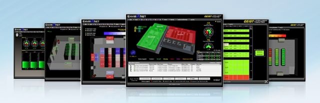
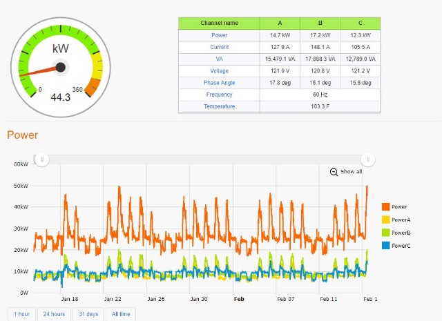
Whether monitoring by cable, bus or radio, all measurement data on power and the environment is usually routed via gateways or central administration units and made available in the first instance via a system-specific, mostly web-based administration tool.
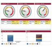
Depending on the manufacturer and system, the data can be organized and viewed in tables and dashboards or via 3D maps. Max and his colleagues always have current and trend reports on power usage at building, room, rack or device level and on environmental parameters for each room, per row of racks, rack or for the different levels and heights in the individual cabinets. In addition, consumption values for company-critical IT devices, the utilisation of distributions and individual outlets as well as temperature, pressure and humidity values on the racks, electricity costs and CO2 emissions can be read.
It is also important that the management platform used supports pre-definition of threshold values for critical power and environmental values so that automatic warning messages are triggered via SNMP or email if these are exceeded. If the management tools of the monitoring solutions offer integration into an existing DCIM solution, extended functions for user and device management, reporting features, data analysis, troubleshooting and optimisation actions are available.
Extensions and system maintenance
While very simple monitoring solutions use the daisy-chaining method, they are often limited in terms of the number of monitoring points that can be integrated and the total distance that can be covered. In the case of the physically connected systems, sensors can be added to the 8, 16 or 32 connection ports of the central control unit, which are usually provided until the control unit is full. Theoretically, these wired solutions are scalable by adding new control units and sensors.
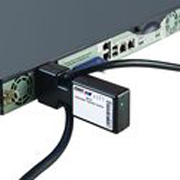
Wireless systems, on the other hand, use a gateway as the central control. The gateway collects and transfers the data from up to 100 wireless measurement modules. The number of monitoring sensors can be expanded as needed by adding additional gateways. Each gateway needs only one IP address, while wired systems very often require an IP address for each individual measurement sensor. The wireless systems are also open to the integration of third-party measurement modules that are already in use via an optionally available hub, provided they communicate via SNMP or Modbus TCP/IP.
System maintenance of cable-based and bus solutions is usually carried out via the central control units via the web or storage media. With the wireless radio system, firmware upgrades can be automatically installed on all system modules via radio or via the web using the management tool.
Failure protection and data security
Just as the entire data centre environment in which Max Z. works has built in redundancy, there is a requirement that the operation of the monitoring system should also be sufficiently protected against network disruptions or power supply interruptions. With the more powerful cable and bus systems, the central control units are usually equipped with a redundant power supply. The recorded measurement data is provided with a time stamp, logged and stored either locally, on multiple storage media or – if permitted – in a secure cloud.
In a wireless solution, data is backed up in a similar way. Protection against failure is established with a back-up gateway. In addition to a primary gateway, one or more back-up gateways can be connected to a different power supply path than the primary gateway. The gateways cyclically synchronise their data with each other at very short intervals. If a gateway fails due to a power supply path or network failure, all measurement data is retained via the backup instances. Data collected locally on the radio measurement modules are protected by a keep-alive function in the event of a power failure.
Transfer of the measurement data can be encrypted with the wireless system just as with physically connected solutions. It is also worth mentioning that, according to the manufacturer, the dynamic radio frequency band used in the proprietary Packet Power system (not ZigBee or WLAN) has a high level of interference immunity and there is no interference with other devices in the data centre.
Administrator Max’s conclusions
There are a few solutions on the market that appear to meet our specified requirements. They can give us what we want, namely valid information about the load distribution in the data center and whether the power consumption and the environmental conditions are in the green. Only a subset of solutions deliver warnings at the thresholds of the critical areas including irregularities or overloads in the supply, power increases, unfavorable temperature developments and other critical environmental conditions. They can help us be more energy efficient by showing which power supply path and racks have power reserves and where there is an opportunity to install additional hardware without impact.
Personally, I find the radio-based Packet Power monitoring solution pretty sexy for the following reasons: Firstly, because it can obviously cover the entire range of services we require. Secondly, it could save us a lot of work and effort thanks to the simple and cable-free installation as well as the automatic self-configuring monitors. Thirdly, I like that it offers useful functions for data backup and failover protection as well as many performance reserves and expansion options for future deployments. And last but not least, the monitoring system is able to exactly quantify the energy and CO2 savings for every efficiency-enhancing measure that we deploy and provide corresponding indicators for evaluation.
I’m ready to present my boss with the business specifications, available options and my recommendations for our data centre’s monitoring system. I’m confident he has the right information to choose wisely.
To dive deeper into this subject and for more best practices to optimise your data centre infrastructure, please contact us on +44 (0)20 8991 6200 or via info.uk@daxten.com.